

Description
Hansen 115mm Weighted HiViz Threaded Ball (Weight included) suits HLEVELLERS / HLVWFLOAT
This is a spare part or replacement weighted float only for Hansen Leveller Valve (HLEVELLERS) use.
SPECIFICATIONS
- PRODUCT CODE: HLVWFLOAT
- CODE MEANING: HANSEN LEVELLER VALVE – WEIGHTED FLOAT
- MATERIALS:
- THREAD INSERT: Glass Fibre Reinforced Nylon
- FLOAT: High Density Polyethylene
- FLOAT ARM: Glass Fibre Reinforced Nylon
- SUITS: Hansen Leveller Valve
- Hansen Leveller Valve is AS/NZS 4020:2018 Approved Product, refer to Hansen Australia Website to see certificate.
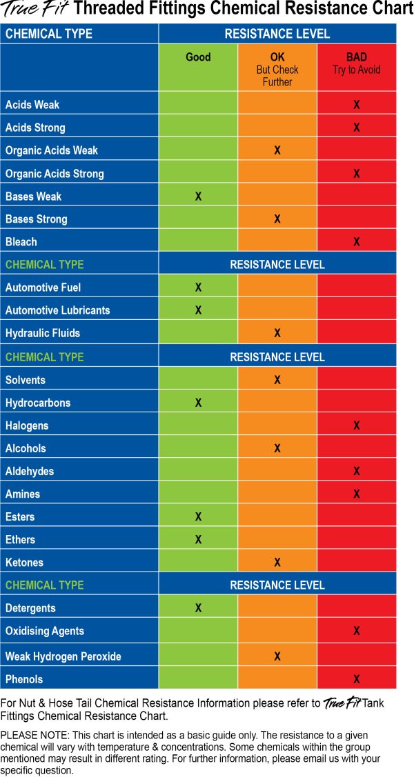
- CHEMICAL RESISTANCE OF HANSEN LEVELLER VALVE
- Please refer to the attached images for full chart of chemical resistance.
Other spare parts that suits the Leveller Valve are available as seperate purchase
- HMFBODY 25mm Valve Body
- HMFDIA 25mm Diaphragm with Stainless Steel Spring
- HLVNUTO Leveller Valve Body Cap Nut
- HLVCAPASS Leveller Cap Assembly
- HLVPHASS Leveller Plunger Housing Assembly
- HLVCLAMPSET Leveller Clamp Set
- HLVHARMASS Leveller Housing & Arm Assembly
- HLVPIN40 40mm Stainless Steel Pin
- HLVCORD Leveller 2.4M Cord & Nut
- HFLOAT140B 140mm Threaded Float, Blue
- HMA15 25x15mm Standard Adaptor with O-Ring Seal
- HMA20 25x20mm Standard Adaptor with O-Ring Seal
- HMA25 25x25mm Standard Adaptor with O-Ring Seal
- HMA32 25x32mm Standard Adaptor with O-Ring Seal
- HMA40 25x40mm Standard Adaptor with O-Ring Seal
- HMA50 25x50mm Standard Adaptor with O-Ring Seal
- HMAL15 25x15mm Long Tail Adaptor with O-Ring Seal
- HMAL20 25x20mm Long Tail Adaptor with O-Ring Seal
- HMAL25 25x25mm Long Tail Adaptor with O-Ring Seal
- HMAL32 25x32mm Long Tail Adaptor with O-Ring Seal
- HMAL40 25x40mm Long Tail Adaptor with O-Ring Seal
- HMAL50 25x50mm Long Tail Adaptor with O-Ring Seal
LEVELLER VALVE INSTALLATION INSTRUCTIONS (Refer to the visual instruction guide in image gallery)
- Step 1a: Measure the existing inlet thread to determine which size adaptor is required (example: 32mm, 40mm, 50mm)
- Step 1b: From the supplied adaptors choose the appropriate size.
- Step 2a: Screw selected adaptor into Leveller Valve Body (O-Ring facing
to body).
- Step 2b: Inspect inside of tank to determine if there is enough clearance to install assembled valve. If yes, go to step 6. If not, go to step 3.
- Step 3a: NOT ENOUGH CLEARANCE. Remove the Leveller Valve Orange nut, arm assembly & rubber diaphragm from valve.
- Step 3b: Screw Leveller Valve body into threaded inlet.
- Step 4a: Re-assemble Leveller Valve, insert rubber diaphragm into valve body.
- Step 4b: Guide Leveller Valve assembly into Leveller Valve body ensuring guide pin is in pilot hole. Do Not Puncture Diaphragm!
- Step 5a: Ensure leveller arm is hanging down in a vertical position and that valve body is horizontal to the tank wall.
- Step 5b: Tighten Orange Nut firmly!
- Step 6: Decide on Minimum and Maximum water levels. See step 9 for minimum level guidance before proceeding through this step. Screw blue float onto Leveller Valve Arm for OFF position. The float can be moved up and down the arm. This determines Maximum level of water.
- Step 7a: Screw cord nut into HiViz Weighted Ball
- Step 7b: Ensure the HiViz Weighted Ball is filled with water and not hindered by any obstructions.
- Step 8a: Thread the string through the end of arm hole, then tie off at cleat to set Minimum level.
- Step 8b: Remove excess string, leaving enough for future fine tuning.
- Step 9: NOTE: The HiViz Weighted Ball must be off the bottom of the tank and most importantly above tank outlet.
- Step 10a: Ensure valve is operating in open/closed position as required. NOTE: the Leveller arm may be in the closed position but the valve may take up to 8 seconds to fully close. Do not force arm closed.
- Step 10b: Fine tuning can be achieved by adjusting the Blue Float up and down the arm and adjusting the length of the string for the on position.
HANSEN LEVELLER VALVE BROCHURE AND CHEAT SHEETS
- For HANSEN Leveller Valve Brochure and Cheat Sheets, refer to Hansen Australia Website.
HANSEN LEVELLER VALVE VIDEO GUIDES & COMMERCIALS
- For HANSEN Leveller Valve Video Guides and Commercials, refer to Hansen Australia Website.
FREQUENTLY ASKED QUESTIONS
- QUESTION: I have noticed my pump switching
on and off rapidly at times, will your Leveller Valve stop this?- ANSWER: Yes, this is called cycling and can
drastically reduce the life of your pump. The Hansen Leveller Valve is designed to control your pump safely by eliminating pump cycling and providing an adjustable water differential depth in your tank.
- QUESTION: I only irrigate from my tank at night
and have a timer on my bore pump. It will only fill my tank at night when I’m irrigating but I still find my bore pump is cycling when I’m irrigating. Will the Hansen Leveller Valve help in this situation?- ANSWER: Yes, you will find the reservoir valve
you are using at the moment is only supplying a flow close to your irrigation demand, with the Hansen Leveller Valve the flow delivery will be much higher and will allow your bore pump to run for less
time as well as setting a differential in the tank to enable your pump to shut off for sensible periods.
- QUESTION: In my dairy shed at peak water
demand times I find my pump is cycling. As demand increases they run continuously and often cannot keep up, resulting in no water in
troughs and other areas in my shed. Will your Leveller Valve fix this issue?- ANSWER: Yes, as long as your pumps are sized
correctly to cover your peak demand the Hansen Leveller Valve will help by delivering a much higher flow at a much lower pressure e.g. 400kPa (58 psi) = 772 l/min (170 gpm).
- QUESTION: For years now I have had problems
with filling my tanks as my water supply can get very dirty at times. I believe I have purchased every valve on the market and all have let me down at some point, will the Hansen Leveller Valve finally fix my problem?- ANSWER: Yes, our range of HiFlo Valves are
designed to handle dirty water. With the Hansen Leveller Valve which is based on our diaphragm valves it is unique in that it has a pin that cleans the pilot hole in the diaphragm every time it opens
and closes. In addition to that the gap between the diaphragm and the valve body when open is a huge 14mm further reducing potential blockages.